RESPIRA FIWARE
Index of contents
- How to build your own RESPIRA FIWARE station
- Bills of materials
- Assembly
- Programming
- Joining a WiFi network
- Connecting to RESPIRA environmental IoT platform
- Maintenance and calibration
How to build your own RESPIRA FIWARE station
The following are the official bills of materials used in this project. If you don’t find the exact references of course you can use your own ones. Since the spirit of this project is totally open source, users can build this station in very different ways, add improvements and even replace the sensors by new references.
Bills of materials
Users are invited to make their own PCB’s based on the available schematics and gerbers.
Microntroller board
| Reference | Description | Source |
|---|---|---|
| U1 | 30-pin ESP32 NodeMCU board | e-bay, Amazon, Aliexpress, etc. |
| R1, R2 | 10kohm 1/6 W resistor | Mouser, Farnell, DigiKey, etc. |
| C1 | 1uF 10V ceramic capacitor | Mouser, Farnell, DigiKey, etc. |
| C2 | 100nF 10V ceramic capacitor | Mouser, Farnell, DigiKey, etc. |
| J1 | 2-pos 5mm-pitch screw connector | Mouser, Farnell, DigiKey, etc. |
| J4 | Molex 95503-2881 Vertical RJ45 connector | Mouser, Farnell, DigiKey, etc. |
| Enclosure | FIBOX TEMPO TAM131007 | RS, Farnell, etc. |
Sensor board
| Reference | Description | Source |
|---|---|---|
| SI7021 | SI7021 dual temperature and humidity sensor | e-bay, Amazon, Aliexpress, etc. |
| SPS30 | Sensirion particulate matter sensor | Mouser, Farnell, DigiKey, etc. |
| SPS30 connector | ZH 1.5mm JST 5-pole female connector | e-bay, Mouser, Farnell, Digikey, etc. |
| ES1-NO2-50 | NO2 sensor 0-50 ppm | ECSense, Pewatron |
| Enclosure | TFA-Dostmann 98.1114.02 | Amazon |
| Ethernet cable | 30 cm of CAT-6 8-pole Ethernet cable | Local store |
| Monopole wire | Coloured <=0.5mm monopole wire | Local store |
Assembly
All parts have been selected to avoid any surface mount soldering (SMT). This means that anyone with a minimum experience in soldering electronic parts and owning a soldering iron should be able to assemble this station. The main microcontroller board is shown in the image below:
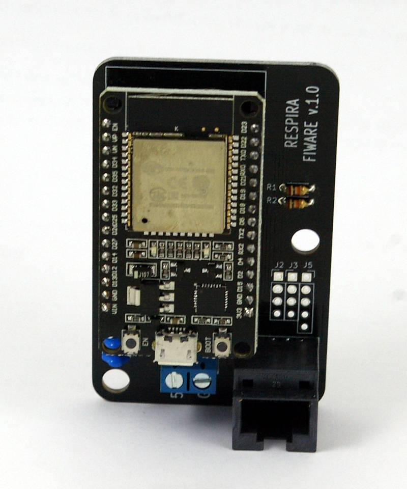
As seen in the above picture, most of the complexity of the electronics is already included in the ESP32 development board. Apart from this main board, the MCU carrier board just needs a few passive components and connectors.
Assembling the sensor board is quite simple as well. Sensor units need to be connected to the auxiliary sensor board with wires. Finally, the sensor board is fixed into the pagoda-style enclosure and connected to the main microcontroller board by means of an Ethernet cable.
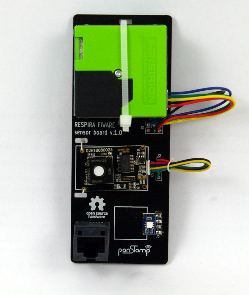
Sensors need to be individually soldered to the sensor board by following this pinout:
<img width=5400" src="../img/sensor_board_pinout.jpg">
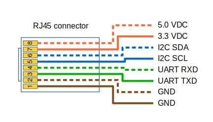
The following pinout diagram is recommended for the Ethernet cable:
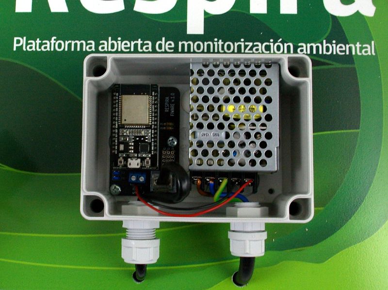
These images show a complete RESPIRA FIWARE station assembled and connected. This station includes a Meanwel 5.0VDC power supply so that the whole electronics can be connected to AC mains:
Programming
The ESP32 is programmed from the Arduino IDE. Before trying to compile the code, the following libraries need to be installed from Sketch->Include library->Manager libraries:
- Paul van Haastrecht’s SPS30 library. This library needs to be installed manually from the repository.
- WiFiManager for ESP32. This library needs to be installed manually from the repository.
- Sparkfun’s SI7021 library. This library can be installed from Arduino’s library manager.
- ArduinoOTA library. This library can be installed from Arduino’s library manager.
We found some problems during compilation due to some conflicts in the libraries for the ESP32 core. These conflicts can be fixed by applying the following changes:
Go to your libraries directory and open sps30/sps30.h. Then comment out INCLUDE_SOFTWARE_SERIAL.
//#define INCLUDE_SOFTWARE_SERIAL 1
After this open WIFIMANAGER-ESP32/WiFiManager.h and rename HTTP_HEAD to HTTP_HEADER:
const char HTTP_HEADER[] PROGMEM = ....
And also rename all the references to HTTP_HEAD in WIFIMANAGER-ESP32/WiFiManager.cpp
Once the above changes have been made, we can finally open respira_fiware from the Arduino IDE. The project is in the directory named as arduino in the project repository. The source code needs to be modified with the FIWARE server IP address, the UltraLight port and the correct API Key to connect your RESPIRA station to the FIWARE IoT agent. If you are connecting the station to our online platform then jump to this section
From respira_fiware.ino:
const char FIWARE_SERVER[] = FIWARE_SERVER_IP_ADDRESS;
const uint16_t FIWARE_PORT = FIWARE_UL_PORT;
const char FIWARE_APIKEY[] = FIWARE_UL_API_KEY;
Finally, select the board ESP32 Dev board from Arduino Tools->Boards, connect the ESP32 board to your computer via USB, select the right serial port and upload the code to the board.
Joining a WiFi network
The code integrates WiFiManager, a popular Arduino library providing a simple web interface to help connect devices to existing WiFi networks. The first time a RESPIRA station is powered on, it deploys a basic WiFi access point with name “RESPIRA_XXXXXXXXXXXX”, being “XXXXXXXXXXXX” the MAC address of the ESP32 module. This access point is also deployed after trying to connect to a precedent WiFi network without success. Once WiFiManager is running we need to follow these steps:
1- Connect to the “RESPIRA_XXXXXXXXXXXX” WiFi network from a cell phone 2- Open the web page http://192.168.4.1. The following interface will appear on the screen:

3- Press on the “Configure WiFi” button 4- Fill SSID and password 5- Save the settings and let the hardware restart
Connecting to RESPIRA environmental IoT platform
Connecting new RESPIRA FIWARE stations to RESPIRA environmental IoT platform is very simple. Once logged into your account you need to create a new device profile and select RESPIRA FIWARE station from the wizard. The platform will return a new API key for this device profile which will have to be entered into the Arduino code.
Once into the Arduino code, set the API key and leave the rest of FIWARE constants unmodified:
const char FIWARE_SERVER[] = "calidadmedioambiental.org";
const uint16_t FIWARE_PORT = 80;
const char FIWARE_APIKEY[] = FIWARE_UL_API_KEY;
Maintenance and calibration
RESPIRA stations need to be periodically maintained. This guide provides some tips about where to install your stations and how to maintain them up to date.